Cold chamber die casting is ideal for metals with high melting points and corrosive properties, like aluminum.
Unlike the hot chamber die casting process, cold chamber solves the corrosion problem by separating the melt pot from the injector components. In the cold-chamber process, metal is transferred by ladle, manually or automatically, to the shot sleeve. Actuation of the injection piston forces the metal into the die—this is a single shot operation. This procedure minimizes the contact time between the hot metal and the injector components, which helps to extend their operating life.
It is possible to cast lower melting point alloys using the cold chamber process but when you consider the advantages of the hot chamber process it usually makes more economical sense to use the hot chamber method for metals like zinc and magnesium.
Components of the Cold Chamber Die Casting Machine
During cold chamber die casting, the molten charge, which consists of more material than is required to fill the casting, is ladled from the crucible into a shot sleeve where a hydraulically operated plunger pushes the metal into the die. The extra material is used to force additional metal into the die cavity to compensate for shrinkage, which takes place during solidification.
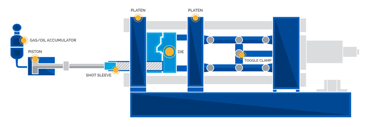
The main components of a cold chamber die casting machine are shown below. Injection pressure of over 10,000psi or 70,000KPa can be obtained from this type of machine.
Operating sequence of the cold chamber die casting process.
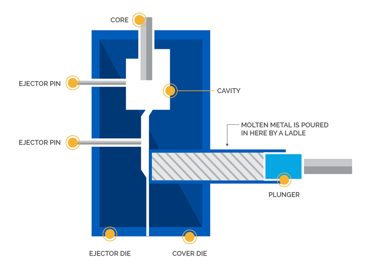
The die is closed and the molten metal is ladled into the cold chamber shot sleeve.
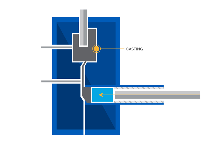
The plunger pushes the molten metal into the die cavity where it is held under pressure until it solidifies.
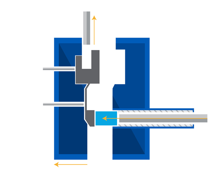
The die opens and the plunger advances, to ensure the casting remains in the ejector die. Cores, if any, retract.
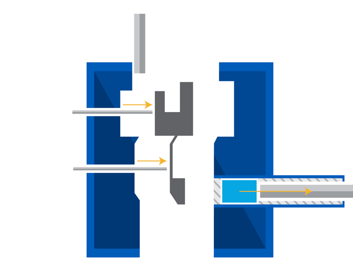
Ejector pins push the casting out of the ejector half of the die and the plunger returns to its original position.
L. M. Chart
Aluminum Alloy and its Spproximate Equivalents
| UK / INDIA | ISO | EN AC- | FRANCE | GERMANY | ITALY UNI | USA AA / ASTM |
USA SAE |
JAPAN |
|---|---|---|---|---|---|---|---|---|
| LM 0 | Al 99.5 | A5 | 3950 | 150 | ||||
| LM 2 | Al-Si10Cu2Fe | 46 100 | A-S9U3-Y4 | 5076 | 384 | 383 | ADC 12 | |
| LM 4 | Al-Si5Cu3 | 45 200 | A-S5U3 | G-AlSi6Cu4 (225) | 3052 | 319 | 326 | AC 2A |
| LM 5 | Al-Mg5Sil AlMg6 | 51 300 | AG6 | G-AlMg5 (244) | 3058 | 514 | 320 | AC 7A |
| LM 6 | Al-Si12 Al-Si12Fe | 44 100 | AS 13 | G-AlSi12 (230) | 4514 | A413 | AC 3A | |
| LM 9 | Al-Si10Mg | 43 100 | A-S10G | G-AlSi10Mg (233) | 3049 | A360 | 309 | AC 4A |
| LM 12 | Al-Cu10Si2Mg | A-U10G | 3041 | 222 | 34 | |||
| LM 13 | Al-Si12Cu Al-Si12CuFe | 48 000 | A-S12UN | 3050 | 336 | 321 | AC 8A | |
| LM 16 | Al-Si5Cu1Mg | 45 300 | A-S4UG | 3600 | 355 | 322 | AC 4D | |
| LM 20 | Al-Si12Cu Al-Si12CuFe | 47 000 | A-S12-Y4 | G-AlSi12(Cu) (231) | 5079 | A413 | 305 | |
| LM 21 | Al-Si6Cu4 | 45 000 | A-S5U2 | G-AlSi6Cu4 (225) | 7369/4 | 308 | 326 | AC 2A |
| LM 22 | Al-Si5Cu3 | 45 400 | A-S5U | G-AlSi6Cu4 (225) | 3052 | 319 | 326 | AC 2A |
| LM 24 | Al-Si8Cu3Fe | 46 500 | A-S9U3A-Y4 | G-AlSi8Cu3 (226) | 5075 3601 | A380 | 306 | AC 4B ADC10 |
| LM 25 | Al-Si7Mg | 42 000 | A-S7G | G-AlSi7Mg | 3599 | A356 | 323 | AC 4C |
| LM 26 | Al-Si9Cu3Mg- | A-S7U3G | 3050 | 332 | 332 | |||
| LM 27 | Al-Si7Cu2Mn0.5 | 46 600 | 7369 | AC 2B | ||||
| LM 28 | Al-Si19CuMgNi | 6251 | ||||||
| LM 29 | Al-Si23CuMgNi | 6251 | ||||||
| LM 30 | Al-Si17Cu4Mg | 390 | ||||||
| LM 31 | Al-Zn5 | 71 000 | A-Z5G | 3602 | 712 | 310 |
Aluminum Alloy and its Recommended end use
| LM 0 | Alloy suitable for Sand Casting, components for Electrical, Chemical and Food Processing Industries. | |||||||
|---|---|---|---|---|---|---|---|---|
| LM 2 | One of the two most widely used alloys for all types of die-castings. | |||||||
| LM 4 | The most versatile of the alloys, has very good casting characteristics and isused for a very wide range of applications. | |||||||
| Strength and Hardness can be grately incresed by Heat Treatment. | ||||||||
| LM 5 | Suitable for Sand and Chill Castings requiring maximul corrosion resistance i.e.castings of marine application. | |||||||
| LM 6 | Suitable for large, intricate and thin walled castings in all types of moulds, also used where corrosion resistance or ductility is required. | |||||||
| LM 9 | Used for allplications especially low pressure die casting requiring the characteristics of LM 6 with higher tensile strength after heat treatment. | |||||||
| LM 12 | Mainly used for sand and chill castings requiring high strength and shock resistance. Requires special foundry techniques and heat treatment. | |||||||
| LM 13 | Mainly used for piston and applications where thermal stresses are more. This alloy can witstand higher termperatures and loads.It has good wear resistance properties and machinability. Requires heat treatment. | |||||||
| LM 16 | Suitable where high mechanical properties are desired in fairly intricate sand and chill castings. Requires heat treatment. | |||||||
| LM 20 | Mainly used for pressure die casting. Similar to LM 6 but with better machinability and hardness. | |||||||
| LM 21 | Generally similar to LM 4M in character and application but better machinability and proof strength. | |||||||
| LM 22 | Used for chill castings requiring good foundry characteristics and good ductility. Requires heat treatment. | |||||||
| LM 24 | Suitable for large, intricate and thin walled castings in all types of moulds, also used where corrosion resistance or ductiity is required. | |||||||
| LM 25 | Suitable where good corrosion resistance combined with thermal properties are required. Strength is attained by heat treatment. | |||||||
| LM 26 | Mainly used for pistons as alternate to LM 13. | |||||||
| LM 27 | A versatile sand and chill cast alloy introduced as an alternative to LM 4 and LM 21. | |||||||
| LM 28 | Piston alloy with lower coefficient of thermal expansion than LM 13. This alloy use requires special foundry technique. | |||||||
| LM 29 | Same characteristics as LM 28 but with still lower coefficient of thermal expansion than LM 28. | |||||||
| LM 30 | For unlined die cast cylinder blocks with low expansion and excellent wear resistance. | |||||||
| LM 31 | ||||||||
Chemical Compositon of Alloys (As per BS 1490:1988 Std.)
| Alloy | Cu | Mg | Si | Fe | Mn | Ni | Zn | Pb | Sn | Ti | Additional Elements |
Others |
|---|---|---|---|---|---|---|---|---|---|---|---|---|
| LM 0 | 0.03 | 0.03 | 0.3 | 0.4 | 0.03 | 0.03 | 0.07 | 0.03 | 0.03 | Al 99.50 min | ||
| LM 2 | 0.7 – 2.5 | 0.3 | 9.0 – 11.5 | 1 | 0.5 | 0.5 | 2 | 0.3 | 0.2 | 0.2 | 0.5 | |
| LM 4 | 2.0 – 4.0 | 0.2 | 4.0 – 6.0 | 0.8 | 0.2 – 0.6 | 0.3 | 0.5 | 0.1 | 0.1 | 0.2 | 0.2 | |
| LM 5 | 0.1 | 3.0 – 6.0 | 0.3 | 0.6 | 0.3 – 0.7 | 0.1 | 0.1 | 0.05 | 0.05 | 0.2 | 0.2 | |
| LM 6 | 0.1 | 0.1 | 10.0 – 13.0 | 0.6 | 0.5 | 0.1 | 0.1 | 0.1 | 0.05 | 0.2 | 0.2 | |
| LM 9 | 0.2 | 0.2 – 0.6 | 10.0 – 13.0 | 0.6 | 0.3 – 0.7 | 0.1 | 0.1 | 0.1 | 0.05 | 0.2 | ||
| LM 12 | 9.0 – 11.0 | 0.2 – 0.4 | 2.5 | 1 | 0.6 | 0.5 | 0.8 | 0.1 | 0.1 | 0.2 | 0.2 | |
| LM 13 | 0.7- 1.5 | 0.8 – 1.5 | 10.5 – 13.0 | 1 | 0.5 | 1.5 | 0.5 | 0.1 | 0.1 | 0.2 | ||
| LM 16 | 1.0 – 1.5 | 0.4 – 0.6 | 4.5 – 5.5 | 0.6 | 0.5 | 0.25 | 0.1 | 0.1 | 0.05 | 0.2 | ||
| LM 20 | 0.4 | 0.2 | 10.0 – 13.0 | 1 | 0.5 | 0.1 | 0.2 | 0.1 | 0.1 | 0.2 | ||
| LM 21 | 3.0 – 5.0 | 0.1 – 0.3 | 5.0 – 7.0 | 1 | 0.2 – 0.6 | 0.3 | 2 | 0.2 | 0.1 | 0.2 | ||
| LM 22 | 2.8 – 3.8 | 0.05 | 4.0 – 6.0 | 0.6 | 0.2 – 0.6 | 0.15 | 0.15 | 0.1 | 0.05 | 0.2 | ||
| LM 24 | 3.0 – 4.0 | 0.3 | 7.5 – 9.5 | 1.3 | 0.5 | 0.5 | 3 | 0.3 | 0.2 | 0.2 | ||
| LM 25 | 0.2 | 0.2 – 0.6 | 6.5 – 7.5 | 0.5 | 0.3 | 0.1 | 0.1 | 0.1 | 0.05 | 0.2 | ||
| LM 26 | 2.0 – 4.0 | 0.5 – 1.5 | 8.5 – 10.5 | 1.2 | 0.5 | 1 | 1 | 0.2 | 0.1 | 0.2 | ||
| LM 27 | 1.5 – 2.5 | 0.35 | 6.0 – 8.0 | 0.8 | 0.2 – 0.6 | 0.3 | 1 | 0.2 | 0.1 | 0.2 | ||
| LM 28 | 1.3 – 1.8 | 0.8 – 1.5 | 17.0 – 20.0 | 0.7 | 0.6 | 0.8 – 1.5 | 0.2 | 0.1 | 0.1 | 0.2 | ||
| LM 29 | 0.8 – 1.3 | 0.8 – 1.3 | 22.0 – 25.0 | 0.7 | 0.6 | 0.8 -1.3 | 0.2 | 0.1 | 0.1 | 0.2 | ||
| LM 30 | 4.0 – 5.0 | 0.4 – 0.7 | 16.0 – 18.0 | 1.1 | 0.3 | 0.1 | 0.2 | 0.1 | 0.1 | 0.2 | ||
| LM 31 | 0.1 | 0.5 – 0.75 | 0.25 | 0.5 | 0.1 | 0.1 | 4.8 – 5.7 | 0.05 | 0.05 | 0.2 |